Introduction
VLAN stands for Virtual Local Area Network. On the Cisco switch in this lab, the default Layer 2 access ports belong to VLAN 1.
I can put ports into different VLANs. Think of this as dividing one physical switch into several logical switches. Each VLAN has its own broadcast domain: the group of devices that can receive the same Layer 2 broadcast.
The switch forwards frames within a VLAN. To send traffic from one VLAN to another, I need a Layer 3 device.
An 802.1Q tag tells the receiving device which VLAN a frame belongs to. For example, one trunk link can carry both VLAN 10 and VLAN 20. The switch at the other end needs a way to tell them apart.
On a normal access link to a PC, frames are usually untagged. The switch uses the port configuration to place them in the right VLAN.
Older Cisco devices also used a Cisco-only method called ISL. This lab uses IEEE 802.1Q.
Why I use VLANs
VLANs let me split one switched network into separate broadcast domains. Here are three reasons I use them.
- Separate different types of traffic. Hosts in different VLANs cannot communicate directly at Layer 2. Once I enable routing between VLANs, I still need ACLs or firewall rules to control who can reach what.
- Make the network easier to manage. I can group devices by their role or department. During troubleshooting, this helps me know where a frame should go.
- Limit flooding. Broadcasts and other Layer 2 flooded traffic stay within their VLAN. A broadcast storm can still happen, but splitting the network into VLANs limits its reach.
The 802.1Q tag and VLAN ID
An 802.1Q tag is 4 bytes long. It sits just after the source MAC address in an Ethernet frame.
| Field | Size | What it does |
|---|---|---|
| TPID | 16 bits | Tag Protocol Identifier. It identifies the tag type. A common 802.1Q C-Tag uses 0x8100. |
| PCP | 3 bits | Priority Code Point. It carries the Layer 2 priority. |
| DEI | 1 bit | Drop Eligible Indicator. It marks whether a frame may be dropped first during congestion. Older material calls this bit CFI. |
| VID | 12 bits | VLAN Identifier. It identifies the VLAN. |
A 12-bit VID can hold values from 0 to 4095. That does not mean all of these values are usable VLAN IDs. Here is the common Cisco Catalyst layout:
| VID | Use |
|---|---|
0 |
A priority tag. It carries priority information; it does not put the frame in a “VLAN 0.” |
1 |
The default VLAN on these Cisco switches. I can use it, but I cannot delete it. |
2–1001 |
Normal-range Ethernet VLANs that are generally available for user configuration. |
1002–1005 |
Default Cisco VLANs reserved for FDDI and Token Ring. |
1006–4094 |
Extended-range VLANs. Availability depends on the platform, software, and VTP mode. A device may reserve some IDs for its own use. |
4095 |
Reserved. |
Cisco: tag fields and Cisco: VLAN ranges.
Configure VLANs
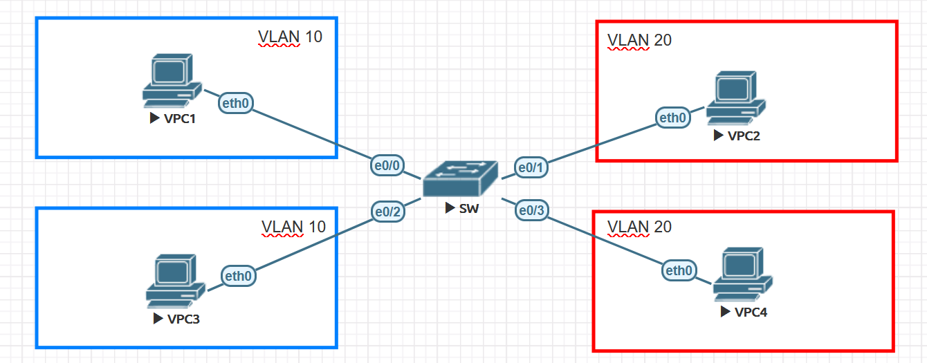
For this lab, I assign VLANs by switch port. First, I create VLAN 10 and VLAN 20. Then I assign the access ports. Here is the topology.
1. Create the VLANs
I create VLAN 10 and name it blue. I create VLAN 20 and name it red.
Switch(config)#vlan 10
Switch(config-vlan)#name blue
Switch(config-vlan)#exit
Switch(config)#vlan 20
Switch(config-vlan)#name red
Switch(config-vlan)#exit
Next, I use show vlan to check that both VLANs exist.
Switch#show vlan

VLAN Name                             Status    Ports
---- -------------------------------- --------- -------------------------------
1    default                          active    Et0/0, Et0/1, Et0/2, Et0/3
10   blue                             active
20   red                              active
1002 fddi-default                     act/unsup
1003 token-ring-default               act/unsup
1004 fddinet-default                  act/unsup
1005 trnet-default                    act/unsup
2. Assign the access ports
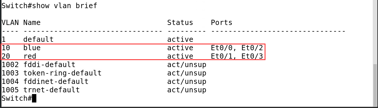
In this topology, Ethernet0/0 and Ethernet0/2 belong to VLAN 10. Ethernet0/1 and Ethernet0/3 belong to VLAN 20.
VLAN 10

Switch(config)#inter ether0/0
Switch(config-if)#switchport mode access
Switch(config-if)#switchport access vlan 10
Switch(config-if)#no shu
Switch(config-if)#exit
Switch(config)#inter ether0/2
Switch(config-if)#switchport mode access
Switch(config-if)#switchport access vlan 10
Switch(config-if)#no shu
Switch(config-if)#exit

VLAN 20

Switch(config)#inter ether0/1
Switch(config-if)#switchport mode access
Switch(config-if)#switchport access vlan 20
Switch(config-if)#no shu
Switch(config-if)#exit
Switch(config)#inter ether0/3
Switch(config-if)#switchport mode access
Switch(config-if)#switchport access vlan 20
Switch(config-if)#no shu
Switch(config-if)#exit
I run show vlan again to check which ports belong to each VLAN.
3. Test VLAN isolation
For this test, I deliberately give all four hosts addresses in 10.1.1.0/24. Each host will treat the others as local neighbors and send ARP requests for them.
This makes it easy to see what happens to an ARP broadcast at a VLAN boundary.
| Host | IP address |
|---|---|
| VPC1 | 10.1.1.1/24 |
| VPC2 | 10.1.1.2/24 |
| VPC3 | 10.1.1.3/24 |
| VPC4 | 10.1.1.4/24 |
From VPC1, I ping VPC3 and then VPC2. I no longer have the original packet capture images for this test. The table below records what I observed in my lab notes.
| Test | VLANs | What I observed |
|---|---|---|
VPC1 → VPC3 (10.1.1.3) |
Both in VLAN 10 | ARP resolved the destination MAC address. ICMP requests and replies passed between the hosts. |
VPC1 → VPC2 (10.1.1.2) |
VLAN 10 → VLAN 20 | VPC1 sent repeated ARP requests but received no reply from VPC2. The ping failed. |
Giving two hosts addresses in the same IP subnet does not put them in the same VLAN. Their ARP broadcasts still cannot cross the VLAN boundary. The logical network looks like this:
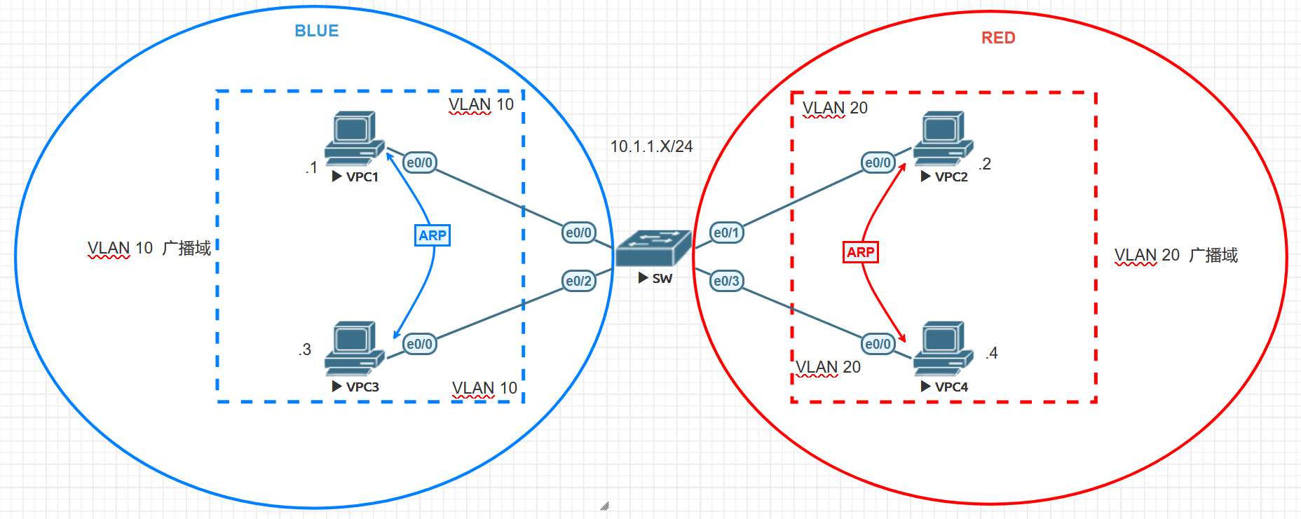
All four hosts use the same IP subnet, but their switch ports belong to two different broadcast domains. VPC1’s ARP request stays in VLAN 10. VPC2, in VLAN 20, never receives it.
In a normal deployment, I usually give different business VLANs different IP subnets. Each subnet can then use its own gateway for routing. I reused the same subnet here only to show how Layer 2 isolation works.
Access, trunk, and hybrid ports
Now let’s look at how these port types handle tags. I use Cisco and Huawei commands as examples.
Access
An access port normally connects to an end device, such as a PC. An untagged frame arriving on the port is placed in its access VLAN. Frames sent to the end device are normally untagged.
Cisco
Switch(config-if)#switchport mode access
Switch(config-if)#switchport access vlan 10

Huawei
[HUAWEI-GigabitEthernet1/0/1] port link-type access
[HUAWEI-GigabitEthernet1/0/1] port default vlan 10
Trunk
A trunk port can carry several VLANs. I often use trunks between switches or between a switch and a virtualization host.
The allowed VLAN list controls which VLANs may use the trunk. In this Cisco 802.1Q lab, outgoing frames in the native VLAN are untagged by default. Outgoing frames in the other VLANs carry a tag.
Cisco
Switch(config-if)#switchport trunk encapsulation dot1q
Switch(config-if)#switchport mode trunk
Switch(config-if)#switchport trunk allowed vlan 10,20

Huawei
[HUAWEI-GigabitEthernet1/0/2] port link-type trunk
[HUAWEI-GigabitEthernet1/0/2] port trunk allow-pass vlan 10 20
Hybrid
On a Huawei hybrid port, I can choose separately for each VLAN whether outgoing frames are tagged or untagged. An incoming untagged frame is placed in the port’s PVID, or Port VLAN ID.
The command below adds VLAN 10 to the list of VLANs sent with a tag.
[HUAWEI] interface gigabitethernet 1/0/3
[HUAWEI-GigabitEthernet1/0/3] port link-type hybrid
[HUAWEI-GigabitEthernet1/0/3] port hybrid tagged vlan 10
The Cisco examples use switchport trunk encapsulation dot1q on interfaces that let me choose the encapsulation. On a platform that supports only 802.1Q, I can go straight to trunk mode.
Cisco: trunk configuration · Huawei: port types
Native VLAN and VLAN 1
In this Cisco lab, VLAN 1 is the default native VLAN on an 802.1Q trunk. With the default tagging behavior:
- Outgoing data frames in the native VLAN are untagged.
- Incoming untagged data frames are placed in the native VLAN.
If I change the native VLAN to 10, the trunk handles untagged data frames as VLAN 10. Both ends must agree on this setting. Some platforms also let me tag outgoing native VLAN traffic.
VLAN 1 is also the default VLAN for Layer 2 access ports on these Cisco switches. In production, I keep user traffic and management traffic separate.
Control protocols need a little more care. How BPDU, VTP, and CDP frames are sent and processed depends on the protocol and platform.
I use show interfaces trunk to check the native VLAN. The example below shows VLAN 10 as the native VLAN and the configuration that sets it. Cisco: trunk and native VLAN troubleshooting
Switch#show inter trunk

Port        Mode             Encapsulation  Status        Native vlan
Et0/0       on               802.1q         trunking      10

interface Ethernet0/0
 switchport trunk allowed vlan 10,20
 switchport trunk encapsulation dot1q
 switchport trunk native vlan 10
 switchport mode trunk
Extend a VLAN across two switches
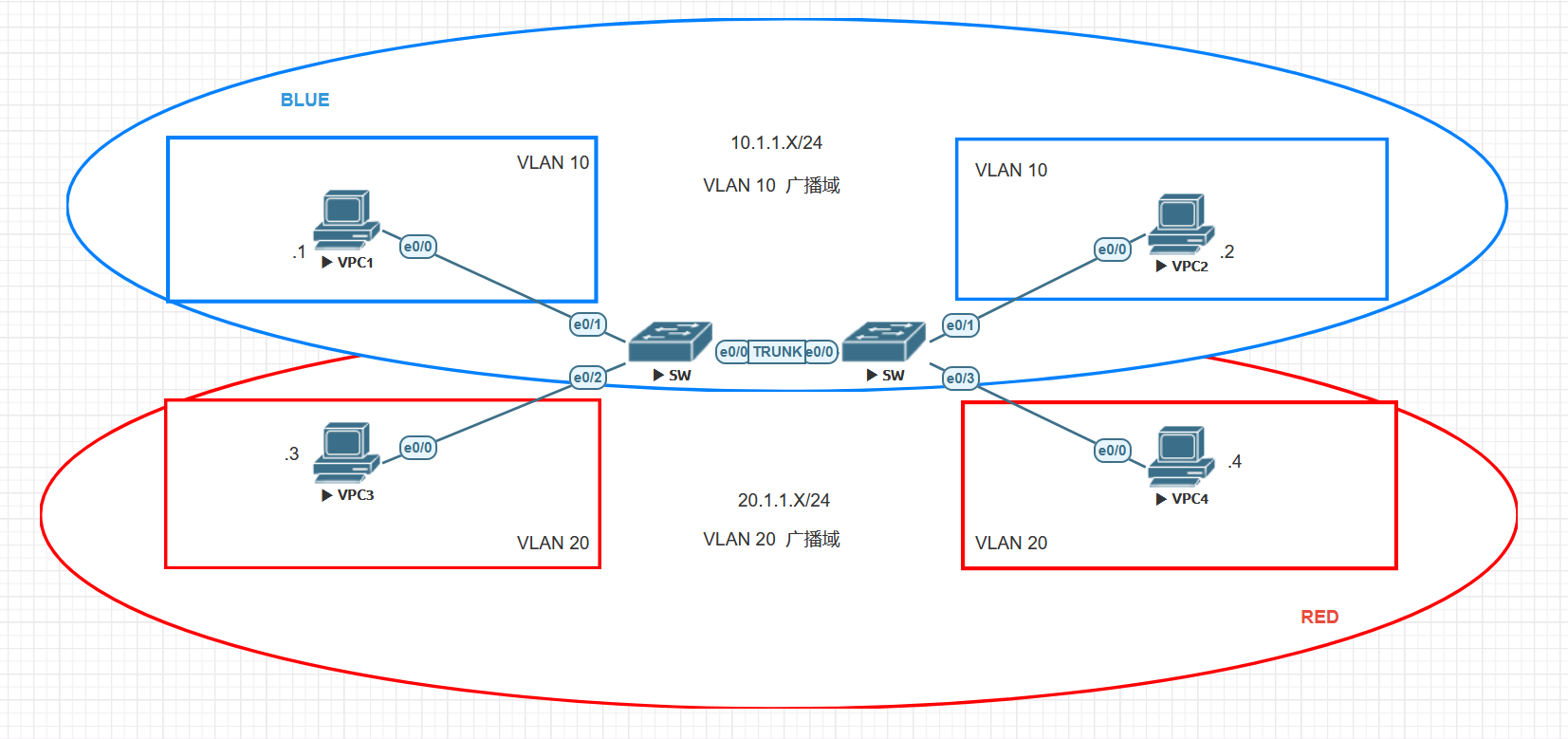
This time, I use two switches. I create the VLANs and assign the access ports on both switches. Then I connect the switches with a trunk.
The goal is simple: hosts in the same VLAN should be able to communicate across that trunk.
1. Create the VLANs on both switches
Switch(config)#vlan 10
Switch(config-vlan)#name blue
Switch(config-vlan)#exit
Switch(config)#vlan 20
Switch(config-vlan)#name red
Switch(config-vlan)#exit
2. Assign the access ports
Left switch

Switch(config)#inter ether0/1
Switch(config-if)#switchport mode access
Switch(config-if)#switchport access vlan 10
Switch(config-if)#no shu
Switch(config-if)#exit
Switch(config)#inter ether0/2
Switch(config-if)#switchport mode access
Switch(config-if)#switchport access vlan 20
Switch(config-if)#no shu
Switch(config-if)#exit

Right switch

Switch(config)#inter ether0/1
Switch(config-if)#switchport mode access
Switch(config-if)#switchport access vlan 10
Switch(config-if)#no shu
Switch(config-if)#exit
Switch(config)#inter ether0/3
Switch(config-if)#switchport mode access
Switch(config-if)#switchport access vlan 20
Switch(config-if)#no shu
Switch(config-if)#exit
3. Configure the trunk
I configure the link between the switches as a trunk at both ends. I allow VLANs 10 and 20, and set the native VLAN to 10 on both switches. This matches the output and captures below.
Switch(config-if)#switchport trunk encapsulation dot1q
Switch(config-if)#switchport mode trunk
Switch(config-if)#switchport trunk allowed vlan 10,20
Switch(config-if)#switchport trunk native vlan 10
4. Check the trunk
On both switches, I use show interfaces trunk to check:
- The link is in the
trunkingstate. - Both ends use the same native VLAN.
- VLANs 10 and 20 are allowed, active, and in the STP forwarding state on the trunk.
Here is an extract from the original lab output. It shows the trunk state and native VLAN.
Switch#show inter trunk

Port        Mode             Encapsulation  Status        Native vlan
Et0/0       on               802.1q         trunking      10
5. Test connectivity
From VPC1, I ping a host in the same VLAN and then one in a different VLAN. At this point, I have configured only Layer 2 switching. There is no inter-VLAN routing yet.
VPC1#ping 10.1.1.2
Type escape sequence to abort.
Sending 5, 100-byte ICMP Echos to 10.1.1.2, timeout is 2 seconds:
!!!!!
Success rate is 100 percent (5/5), round-trip min/avg/max = 1/1/2 ms
VPC1#ping 20.1.1.2
Type escape sequence to abort.
Sending 5, 100-byte ICMP Echos to 20.1.1.2, timeout is 2 seconds:
.....
Success rate is 0 percent (0/5)
6. Compare tagged and untagged frames
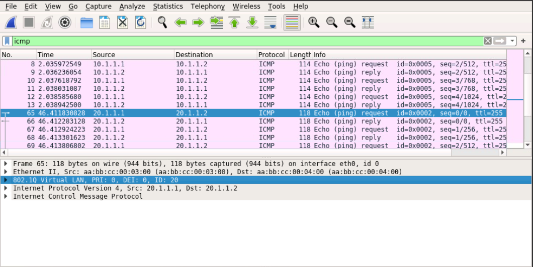
I capture traffic on the trunk between the switches. The selected packet in the first image is an ICMP packet in VLAN 20. Wireshark shows an 802.1Q tag with VID 20.
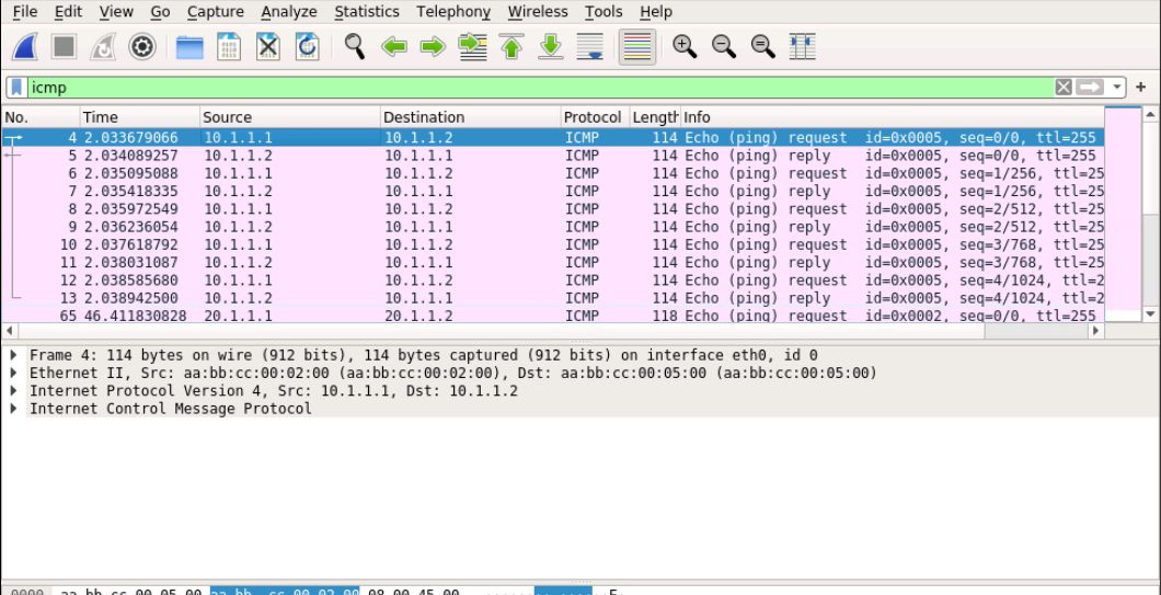
The selected packet in the second image is in VLAN 10. VLAN 10 is the native VLAN in this lab, so this frame has no 802.1Q tag.
These are frames from different VLANs on the same trunk.
Route traffic between VLANs
So far, I have used only Layer 2 switching. To reach another IP subnet, a host sends traffic to its default gateway. The gateway then routes it.
I will use two methods: router-on-a-stick and a Layer 3 switch.
1. Router-on-a-stick
With router-on-a-stick, I connect the switch to a router using one trunk link. On the router, I create an 802.1Q subinterface for each VLAN.
The router looks at the destination IP address and its routing table to choose the outgoing interface. When needed, it uses ARP to find the next-hop MAC address.
This setup uses one physical link. For each packet routed between VLANs, the switch sends the packet to the router. The router sends it back over the same link in the opposite direction.
Inter-VLAN traffic shares the capacity of this link in each direction.
Here is the router-on-a-stick topology.
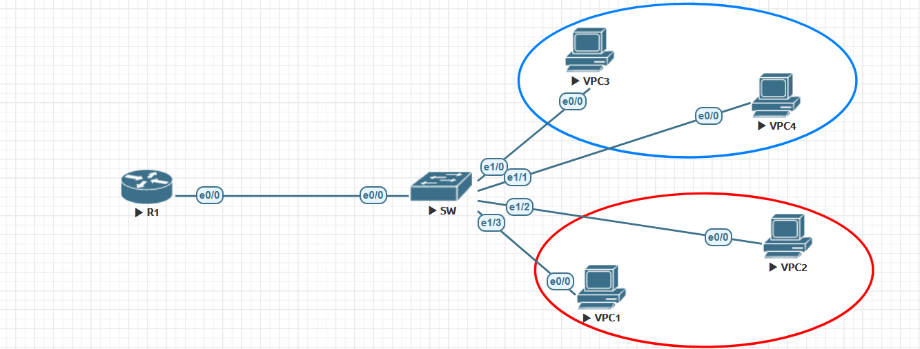
| VLAN | Host addresses | Gateway on R1 |
|---|---|---|
| VLAN 10 (blue) | VPC3 10.1.1.1, VPC4 10.1.1.2 |
10.1.1.254 |
| VLAN 20 (red) | VPC1 20.1.1.1, VPC2 20.1.1.2 |
20.1.1.254 |
Below are the R1 and SW configurations. I first create VLANs 10 and 20 on SW. The switch trunk and the router subinterfaces must agree on tagging.
Hosts in VLAN 10 use 10.1.1.254 as their default gateway. Hosts in VLAN 20 use 20.1.1.254.
R1

interface Ethernet0/0
 no ip address
 duplex auto
!
interface Ethernet0/0.1
 encapsulation dot1Q 10
 ip address 10.1.1.254 255.255.255.0
!
interface Ethernet0/0.2
 encapsulation dot1Q 20
 ip address 20.1.1.254 255.255.255.0


SW
interface Ethernet0/0
 switchport trunk allowed vlan 10,20
 switchport trunk encapsulation dot1q
 switchport mode trunk
!
 interface Ethernet1/0
 switchport access vlan 10
 switchport mode access
!
interface Ethernet1/1
 switchport access vlan 10
 switchport mode access
!
interface Ethernet1/2
 switchport access vlan 20
 switchport mode access
!
interface Ethernet1/3
 switchport access vlan 20
 switchport mode access
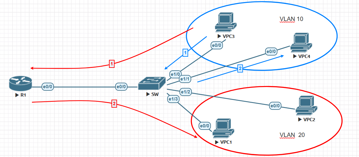
The diagram below follows traffic from VPC3. The blue line stays within the same VLAN, so the switch forwards the frames directly. The red line crosses VLANs. Traffic goes over the trunk to R1, is routed, and comes back to the switch.
2. Use SVIs on a Layer 3 switch
This time, I put the gateways on the switch itself. Cisco calls this Layer 3 VLAN interface an SVI, or Switched Virtual Interface. Huawei calls it a VLANIF.
Some Layer 2 switches also have an SVI for management. That alone does not mean they can route between VLANs. The switch must support Layer 3 routing, and routing must be enabled.
Here is the SVI lab topology.
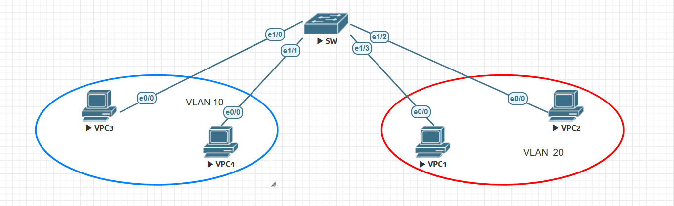
I keep the same VLANs and gateway addresses from the previous lab. This time, I put the gateway addresses on the switch’s VLAN interfaces.
interface Ethernet1/0
 switchport access vlan 10
 switchport mode access
!
interface Ethernet1/1
 switchport access vlan 10
 switchport mode access
!
interface Ethernet1/2
 switchport access vlan 20
 switchport mode access
!
interface Ethernet1/3
 switchport access vlan 20
 switchport mode access
!
interface Vlan10
 ip address 10.1.1.254 255.255.255.0
!
interface Vlan20
 ip address 20.1.1.254 255.255.255.0
I use show ip interface brief to check the SVIs. In the output below, both Vlan10 and Vlan20 are up/up.
Switch#show ip inter brief
Interface              IP-Address      OK? Method Status                Protocol
Ethernet1/0            unassigned      YES unset  up                    up
Ethernet1/1            unassigned      YES unset  up                    up
Ethernet1/2            unassigned      YES unset  up                    up
Ethernet1/3            unassigned      YES unset  up                    up
Vlan10                 10.1.1.254      YES manual up                    up
Vlan20                 20.1.1.254      YES manual up                    up
If an SVI is not up/up, I check these three things. These conditions follow the Cisco Autostate behavior used in this lab:
- The VLAN exists on the switch and is active.
- The SVI is not administratively shut down.
- At least one Layer 2 port that counts toward Autostate carries this VLAN. Its link must be up, and it must be in the STP forwarding state for that VLAN. This can be an access port or a trunk that allows the VLAN.
Each host must also use the correct SVI address as its default gateway. On this Cisco lab platform, I need ip routing if IPv4 routing is not already enabled. Commands and defaults can differ on other platforms. Cisco: SVI Autostate
Switch(config)#ip routing
What I take away from these labs
I find VLAN troubleshooting easier when I follow the frame’s path.
First, I check which VLAN the frame enters. On an access port, the port configuration decides where an untagged frame belongs. If the frame needs to reach another switch, I check that the trunk allows the VLAN. Tagged frames carry a VID. Untagged frames depend on matching native VLAN settings.
If the destination is in another VLAN, I move on to the gateway and routing. With router-on-a-stick, the gateway is a router subinterface. With a Layer 3 switch, it is an SVI.
That is the order I use: access VLAN, trunk, then gateway and routing.
